

Before feeding the wire into the machine, it is essential to manually straighten the first 450–500 mm (approximately 1.5–2 ft) of the wire. This straightened portion helps guide the wire smoothly through the machine and ensures proper entry into the cutting nozzle inside the cutting die box. Failure to straighten the initial length of wire may cause feeding difficulties and affect machine performance.
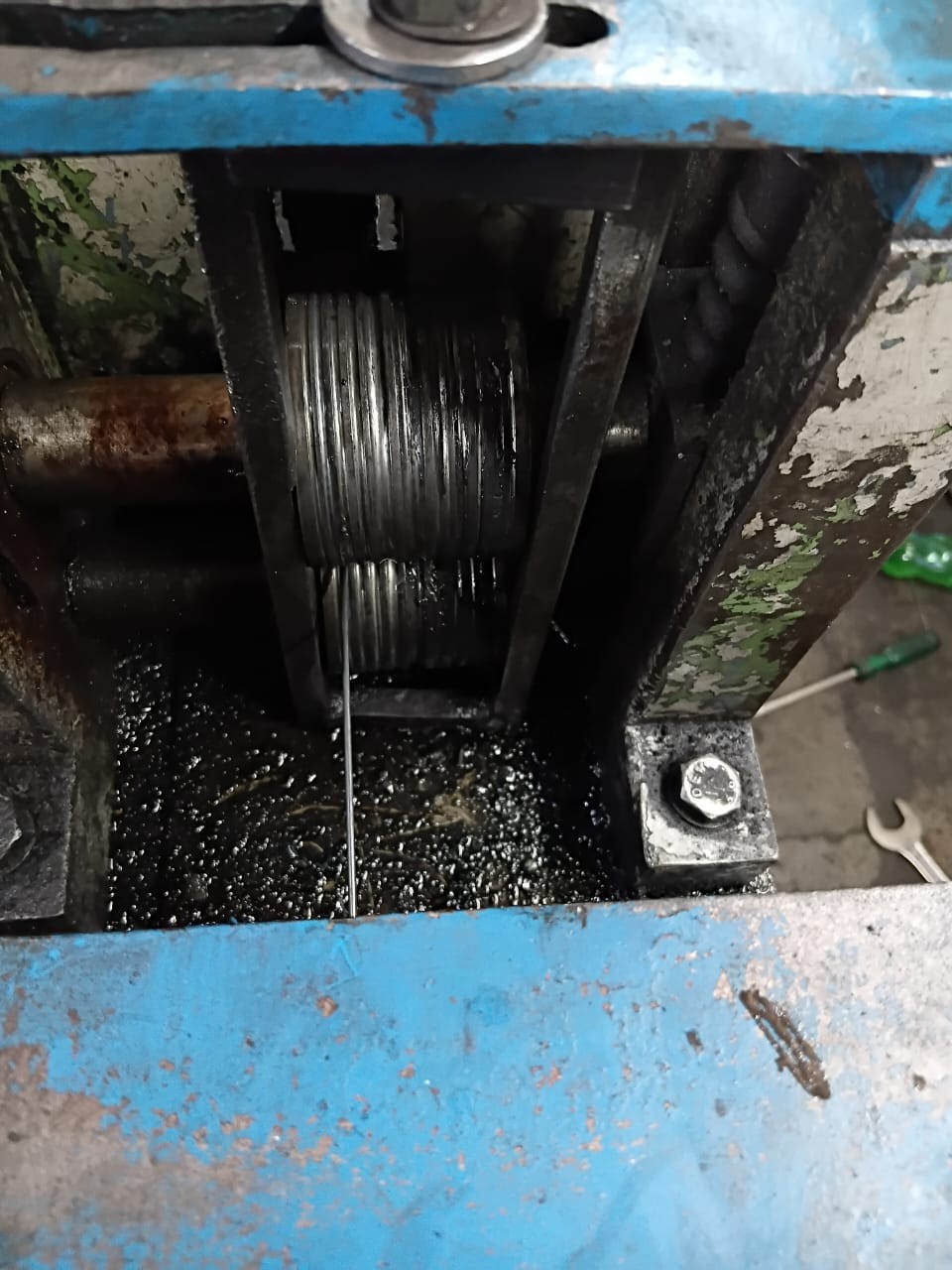
Note: Before performing the above operation, ensure that the correct roller groove is aligned with the centre of the cutting nozzle. For example, when processing 3 mm wire, the 3 mm groove on the roller must be positioned exactly in line with the centre of the cutting nozzle. Incorrect alignment may result in improper wire feeding and reduced machine performance.
Wire straightening does not have any fixed settings or parameters. The straightening dies must be adjusted to apply the required pressure to remove wire bends and achieve a straight output, as shown in the reference image.
The wire is straightened by applying controlled zig-zag pressure through the straightening dies. This process neutralizes the natural bends in the wire, resulting in a straight wire. The amount of pressure required depends on the wire material and its properties. Different wire types, such as MS wire, SS wire, spring steel wire, and others, may require different straightening settings.
Important: Wire straightening must be properly adjusted before setting the final cutting length.
- Before starting the straightening adjustment, lift the front portion of the length patti and place it on a 30 mm support rod.
- This allows you to observe whether the cut pieces are straight.
- Cut and inspect 2–3 sample pieces of approximately 300–400 mm length.
- Set the 1st straightening die and the 5th straightening die at the same height as the bore of the spinner.
- The reference point is the bore (wire passage line) of the spinner, not the centre of the spinner body.
- When the wire enters the spinner, the 1st die should only support and guide the wire. It should not apply pressure to the wire.
- Similarly, the 5th die should support the wire at the exit side.
- Adjust the 2nd, 3rd, and 4th straightening dies in a zig-zag pattern as shown in the reference image.
- These dies are responsible for applying the straightening pressure to the wire.
- Increase or decrease the pressure gradually until the desired straightness is achieved.
It is not necessary that the wire will become perfectly straight on the first attempt. The adjustment process may need to be repeated several times. Check the sample pieces after each adjustment and make small corrections as required. Normally, 2–3 adjustment cycles are sufficient to achieve proper straightness.
Note: Although the straightening procedure may appear complicated when reading these instructions, it is actually simple in practice. After a few adjustments, the operator will easily understand how to obtain the desired wire straightness.
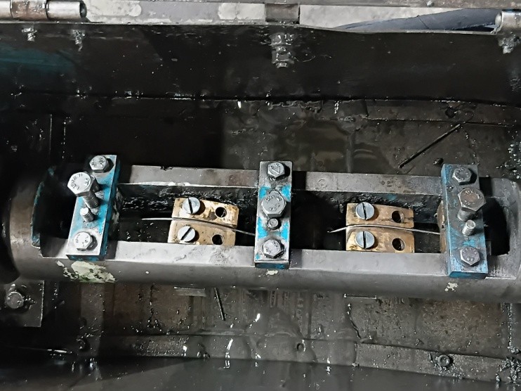
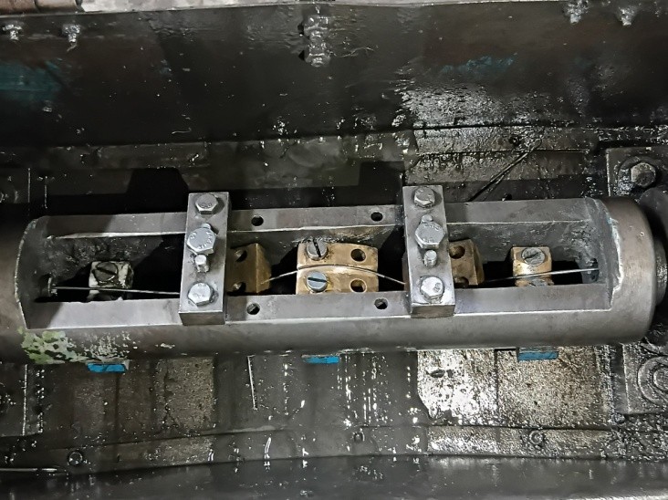
For more details, you can refer to the video below. The video is a bit long, so you can skip to 5:52 to watch the wire straightening setup training.
Watch Video — Wire Straightening SetupBefore performing the above operation, ensure that the correct roller groove is aligned with the centre of the cutting nozzle. For example, when processing 3 mm wire, the 3 mm groove on the roller must be positioned exactly in line with the centre of the cutting nozzle. Incorrect alignment may result in improper wire feeding and reduced machine performance.
The roller alignment can be adjusted easily by gently tapping the roller assembly with a hammer from left to right or right to left until the groove is perfectly aligned with the cutting nozzle.
Before making any alignment adjustments, loosen the bolts of the roller guide that hold the roller assembly in position. Once the correct alignment is achieved, tighten the bolts securely to lock the roller assembly in place.
The cutting nozzle is a critical component and must be selected according to the wire diameter and material type.
For example, when cutting 2 mm Mild Steel (MS) wire, a cutting nozzle with an inner diameter (ID) of 2.8 mm to 3.0 mm is generally recommended. However, for 2 mm Stainless Steel (SS) wire, a 2.5 mm ID nozzle should be used. Using a larger nozzle, such as 3.0 mm ID, for SS wire may result in burr formation on the cut ends of the wire.
After selecting the appropriate cutting nozzle based on the wire diameter and material, install the nozzle in the die box. Next, adjust the cutting blade so that it enters the die box until it just reaches the nozzle position.
Important: Maintain a clearance of 0.1 mm to 0.2 mm between the cutting blade and the cutting nozzle. The clearance should be neither less nor more than this recommended range.
- Excessive clearance may cause burrs and poor cutting quality.
- Insufficient clearance may lead to contact between the blade and nozzle, resulting in damage to the cutting blade, cutting nozzle, or both.
Once the correct clearance is achieved, securely lock the setting using the locking nut (chaki). After completing the adjustment, install the die box on the machine and proceed to the next setup procedure.
| Wire Type | Wire Diameter | Recommended Nozzle ID |
|---|---|---|
| Mild Steel (MS) Wire | 2 mm | 2.8 mm to 3.0 mm |
| Stainless Steel (SS) Wire | 2 mm | 2.5 mm |
This is one of the most critical and challenging procedures in operating a wire straightening and cutting machine, and it requires careful adjustment and operator skill.
For example, consider a wire diameter of 3 mm with a cutting length of 2 ft.
At the top of the length patti, there is an H-shaped square bar holder. Loosen one side of the H-holder by slightly reversing the 8 mm bolt. Normally, 1–2 turns are sufficient to release the pressure and allow adjustment.
The gap between the two square bars of the length patti should be maintained slightly larger than the wire diameter:
- For wire diameters up to 2 mm, maintain approximately 0.5 mm additional clearance.
- For thicker wires, maintain approximately 1 mm additional clearance.
To verify the gap, take a short sample piece of wire (approximately 100 mm long) of the same diameter and slide it through the gap between the two square bars. The wire should move smoothly without excessive force. If the wire binds or moves tightly at any point, recheck and readjust the gap.
A C-clamp can be used during adjustment to hold the square bars in position and maintain a uniform gap along the entire length of the length patti.
Once the correct gap is achieved and verified, securely tighten the 8 mm bolt on the H-holder to lock the setting in place.
Note: Proper gap adjustment is essential for accurate wire feeding and cutting performance.
For a better understanding of this procedure, watch the detailed setup video below.
Watch Video — Wire Cutting Length Setting